I released last week a new version of my dynamo package DynamoMEP. To help you around the new features, I build a few samples making use of these nodes.
Get the opening side of a door
Among the new nodes, the FamilyInstance nodes allow you to use family reference. These references give you access to reference planes contained in the family. In this example, I show you how to use these references to find if a door is opening inside or outside of the room.
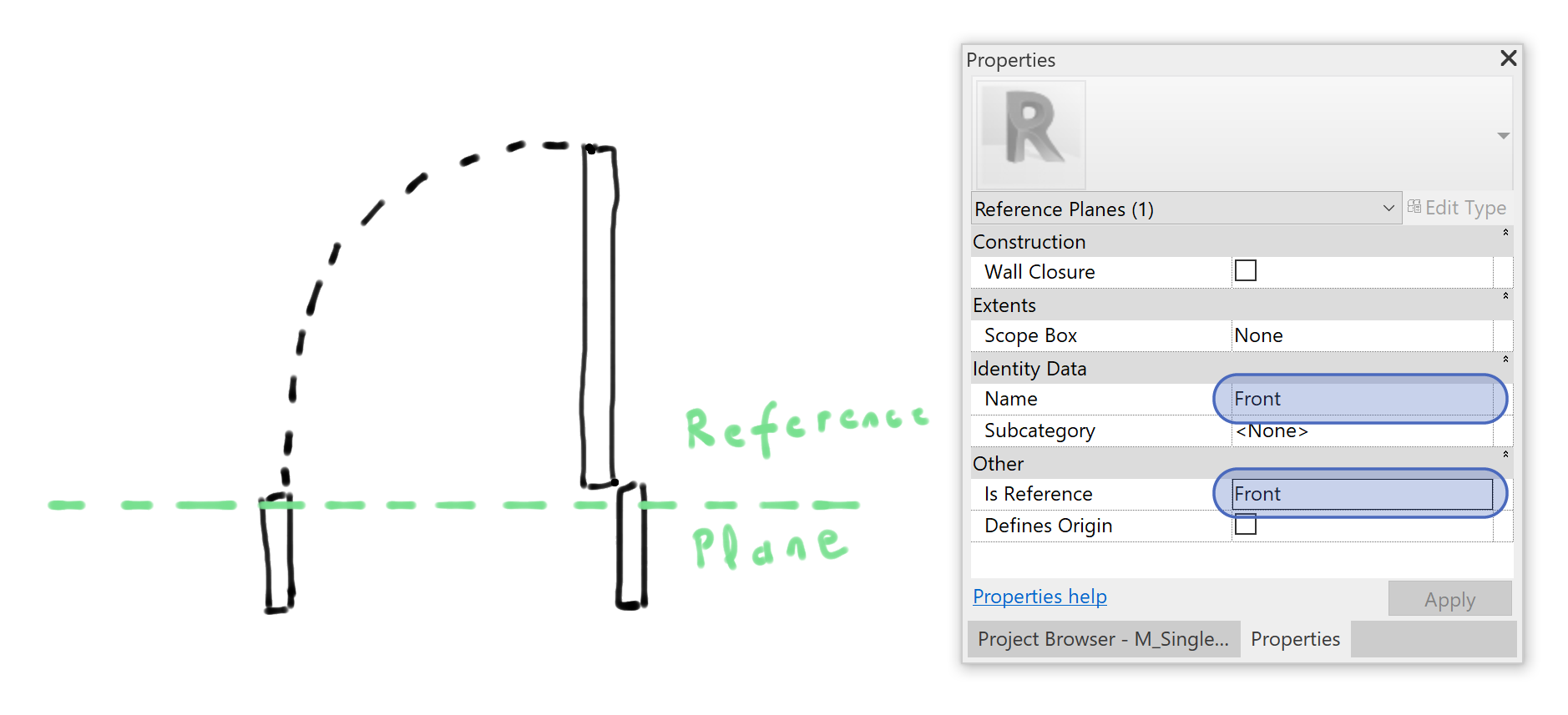
In all door families, I make sure that a “Front” reference plane is positioned on the opening side. In the OOTB Revit families, such a reference plane generally already exists, I change its name and type to “Front”:
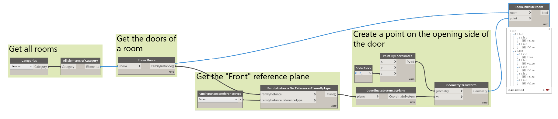
In the model, I retrieve all rooms and use the “Room.Doors” node from DynanoMEP to get all doors associated with a given room. Then, I use the “FamilyInstance.GetReferencesPlanesByType” to get the plane “Front” for every door instance.
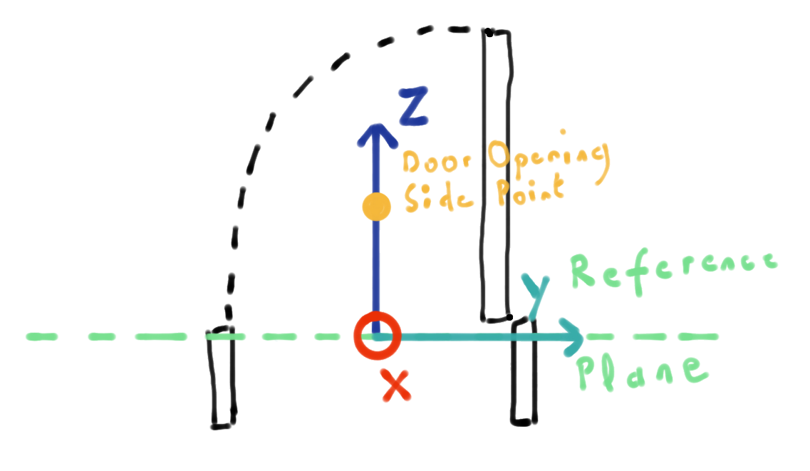
Using “CoordinateSystem.ByPlane”, I get a coordinate system aligned with the door. This coordinate system allows me to create a point placed on the opening side of the door.
To find in which room the door is opening, we just find if the point is in the room or not. I am using the Revit node “Room.IsInsideRoom”. We end up for each room a list of boolean indicating if the associated door is opening in the room or not.
This simple example can be adapted to any family, as long as they contain named reference planes.
The complete definition can be found here.
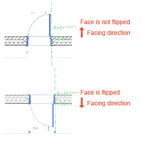
A word about flipped family instance and reference plane
Every family instance can have up to two flip controls, one horizontal (the “Hand” orientation) and one vertical (the “Facing” orientation).
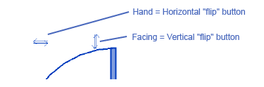
These controls will mirror the family with its centre plane acting as the mirror reference.
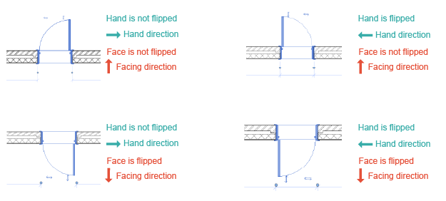
If your reference plane is aligned with the hand or facing direction, flipping the family will not change the orientation of this plane. In all other cases, the plane will be mirrored like the rest of the geometry of the family.
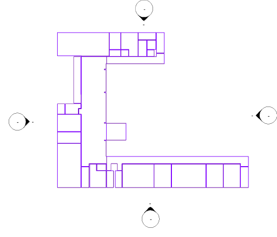
Create area boundaries from a DWG
In France, the legal definition of the building area (“Surface de Plancher”) is slightly different that the area calculated by Revit rooms. For example, we must include in this area the footprint of internal walls and columns. During the development of the project, the Revit room area is enough. But before submitting the building permit, a quantity surveyor must measure a more accurate area. These surfaces are measured with polylines in AutoCAD.
Since I wanted to retrieve these polylines in Revit, I created specific nodes to create Room, Space or Area boundaries in Dynamo.
I import the DWG containing the polylines in Revit and create an “Area - Level 0” area plan to draw my area boundaries in it. The definition is then rather simple, I am using the “CAD.CurvesFromCADLayers” node from BimorphNodes to retrieve the curve from the DWG. I select manually the area plan view and use the « AreaBoundary.ByCurveAndView» to create the area boundaries.
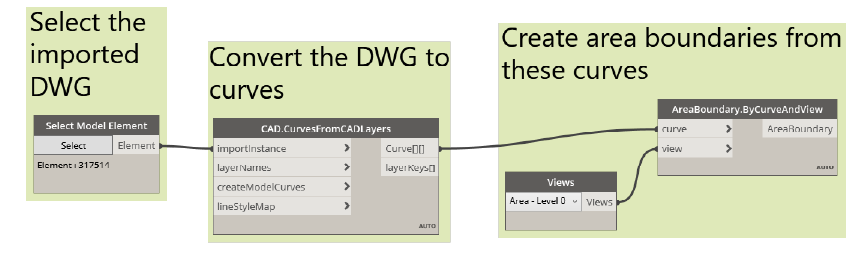
The complete definition can be found here.
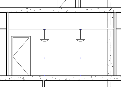
Place lightning fixtures along a grid in a room
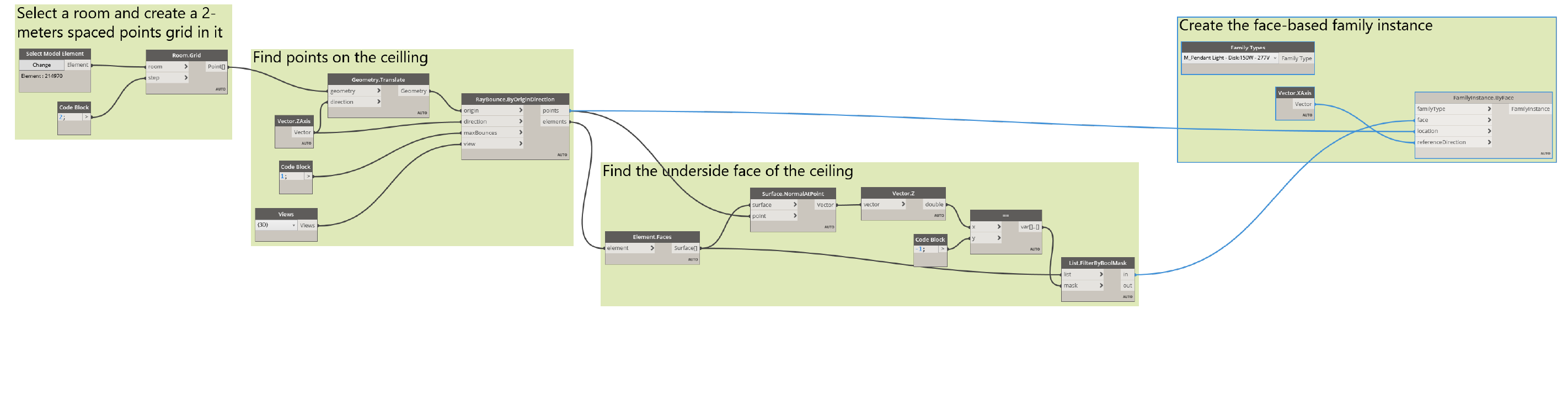
DynamoMEP contains a node to generate a grid of points in a room. These points can be used to create regularly spaced elements in a room. In this example, we use this node to place lighting fixtures in a room.
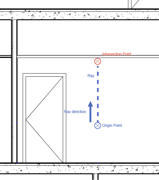
To get the corresponding points on the ceiling, we use the “RayBounce.ByOriginDirection” node. This node will create a “ray” and return the intersection point and the intersecting elements.
We then use these points and elements to get the underside face of the ceiling and place our face-based pendant light family instance:
Obviously, this definition could be adapted for any kind of face-based family.
The complete definition can be found here.
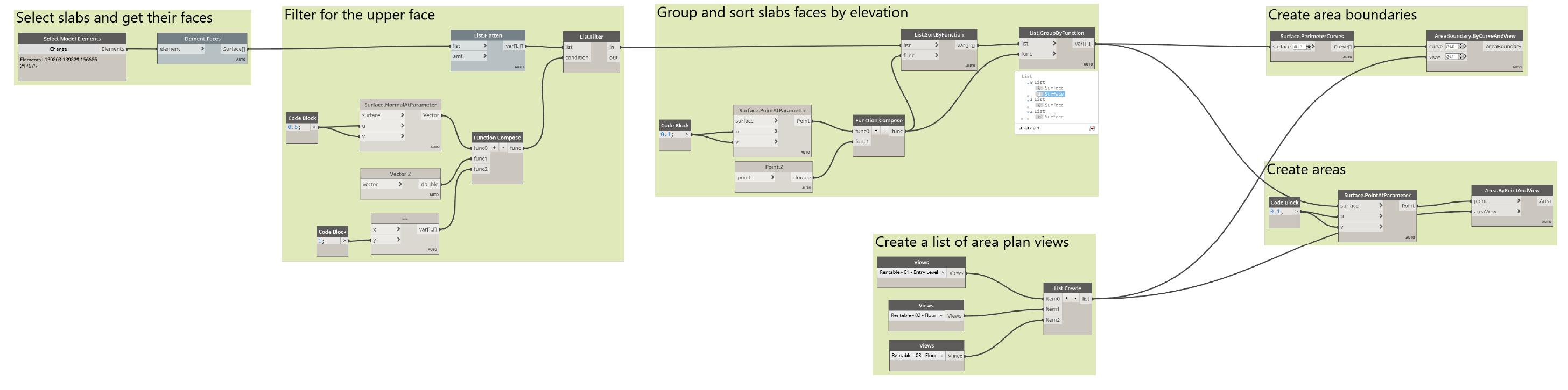
Create areas from floors
The last example aims at answering a question from Tom who wanted to create areas based on a slab profile.
To do so, I start by manually creating an area plan for every level. From a selection of slabs, I extract their faces and find the upper face using the Z coordinate of the normal vector of surface. Using again the “Surface.PointAtParameter”, I find the elevation of each slab and use this value to group and sort slabs by their elevation.
I end up with a group of slab face for each level. I manually create the corresponding list of area plan views in the same order. I extract the boundary curves of the grouped surfaces and use them with my list of area plan to create a series of area boundary on each area view plan.
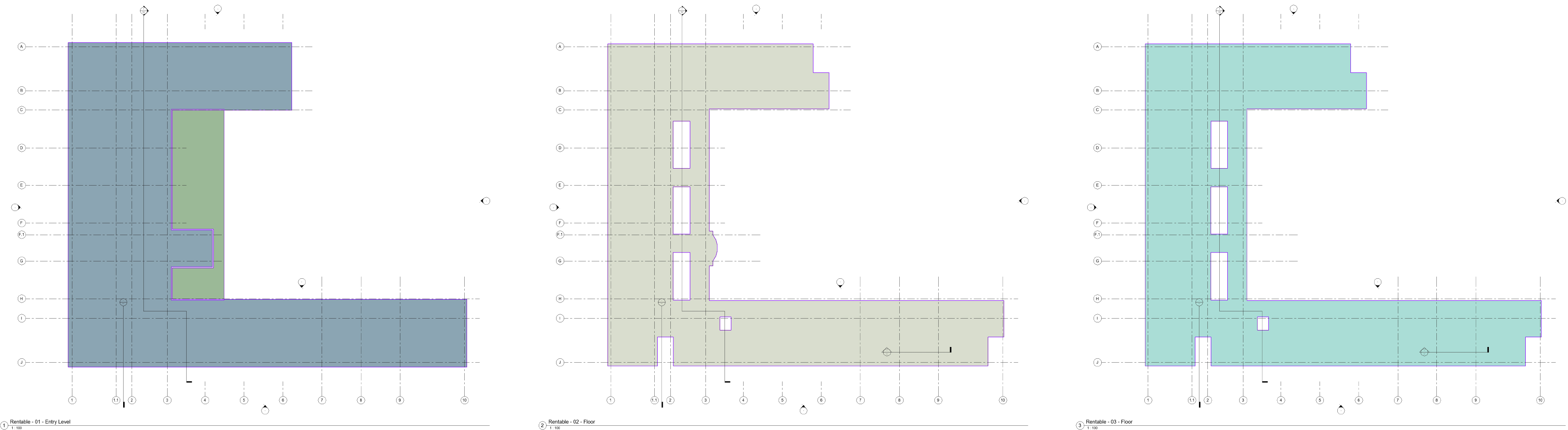
I am then using the same list to create an area for each floor.
The complete definition can be found here.
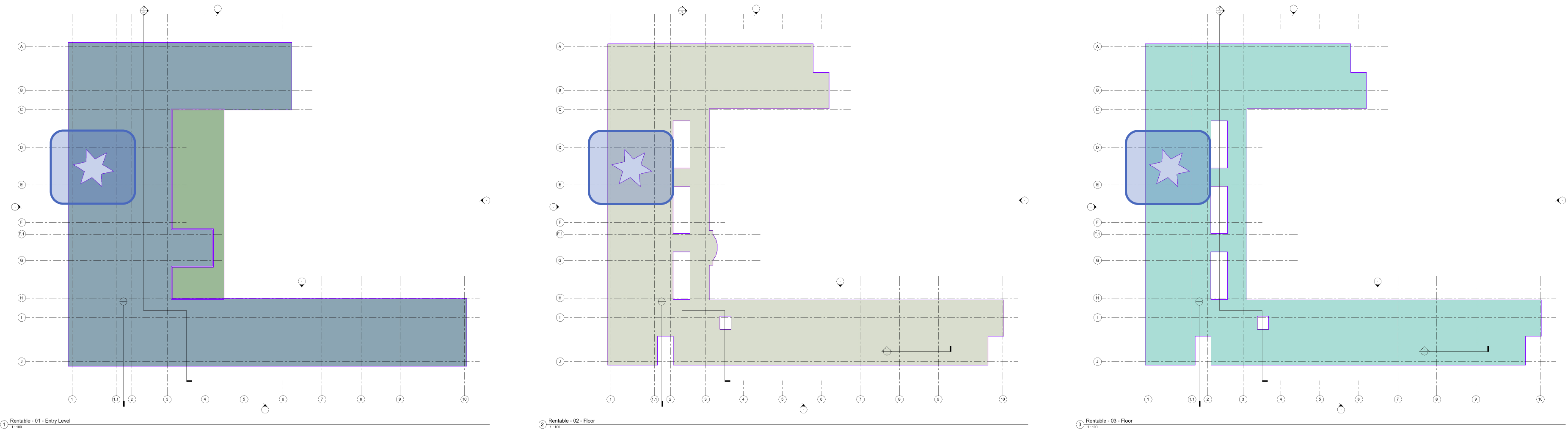
Since the boundaries are linked to the slab geometry, they are updated each time the geometry is updated, like when I create this star-shaped shaft through all levels:
A lot of workflows can make use of DynamoMEP, I hope these few samples will help you getting started with it.