Like many other in the AEC space, I have been following the development of Townscaper, the town-building game made by Oskar Stålberg. Behind this game, there is a lot to learn on how to generate building geometry.
One of the main algorithms used in this game is the Wave function collapse algorithm. Initially developed for generating images from a small input, its principle can be applied to a lot of use cases, like town planning, wedding seating plan and even poetry.
The main idea behind the Wave Function collapse algorithm start from a grid. On this grid, we place an element from a list (a list pixels for generating an image or a list of building/road for generating a town). As we place the first element, a series of rules constrains which elements can be placed nearby on the grid.
I stole the great example from Robert Heaton to explain how this algorithm works.
Let say we want to create a simple landscape. In this landscape, we can have either Land, Sea, Coast or Mountain. Each type of terrain is represented by a square tile:
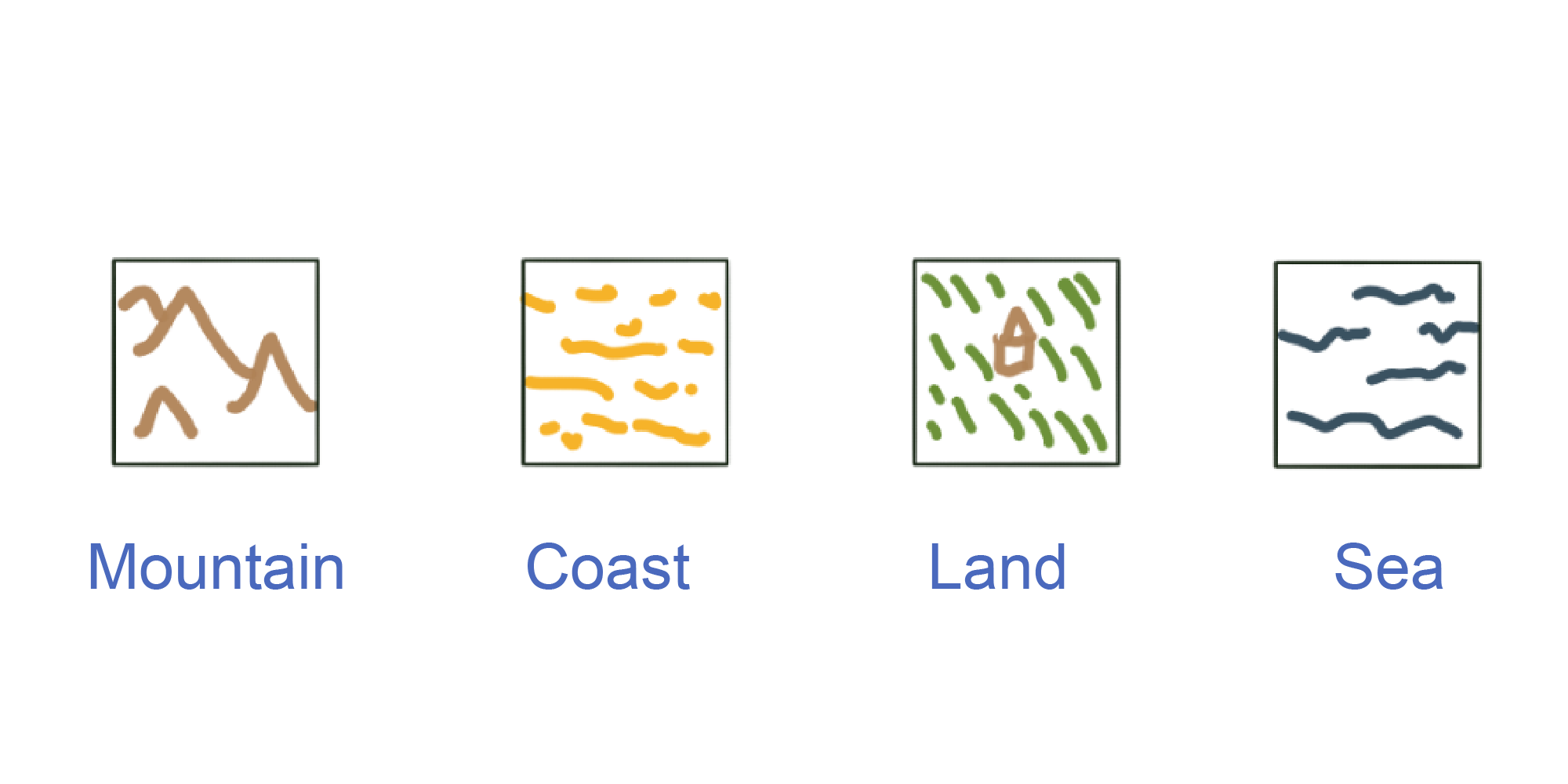
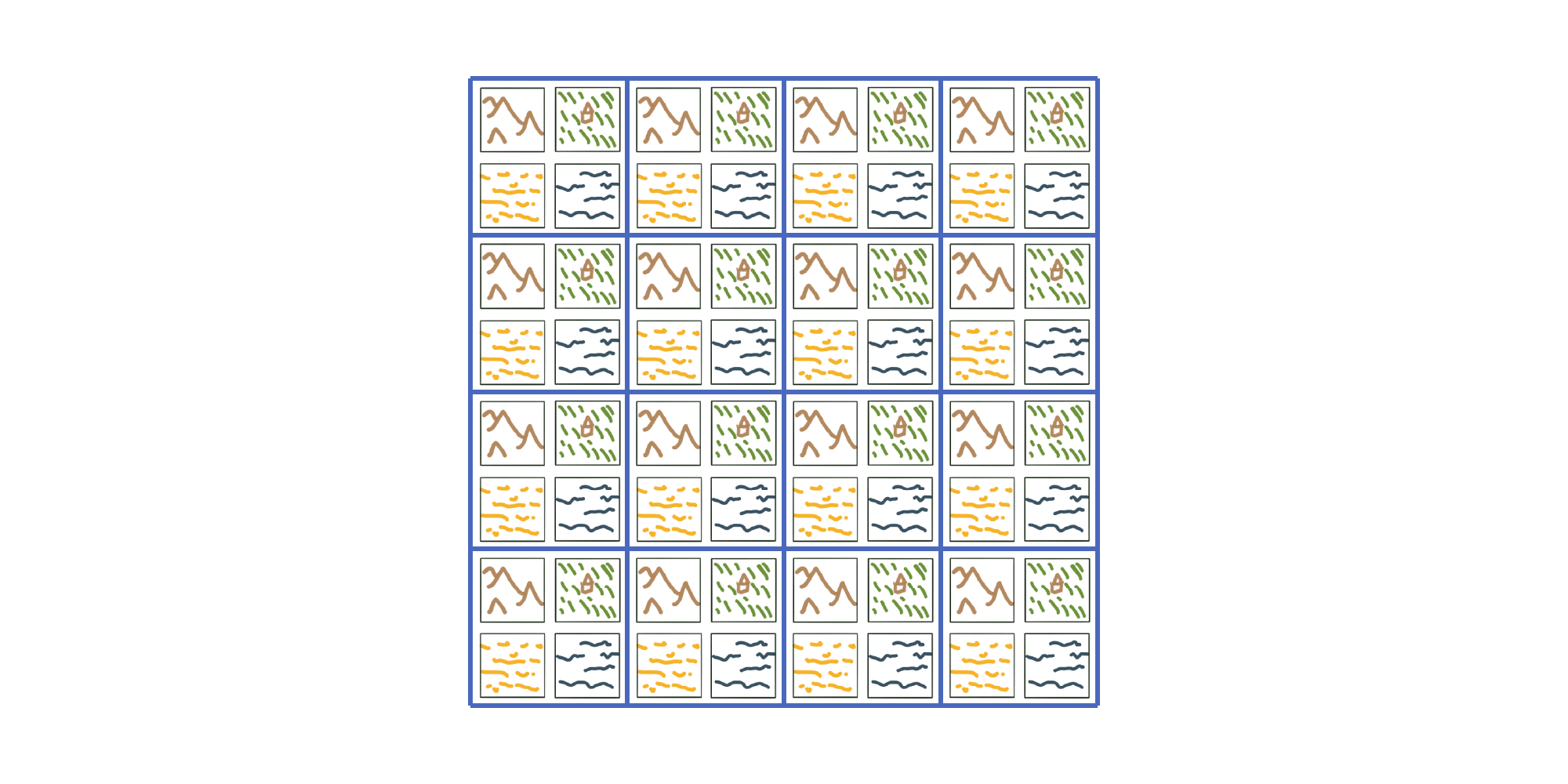
These four tiles can be placed anywhere on a grid:
Then, rules constrain the position of a tile relative to one another. Here,
- Sea can only be near Coast or itself
- Mountain can only be near Land or itself
- Coast must have Land on one side and Sea on the other
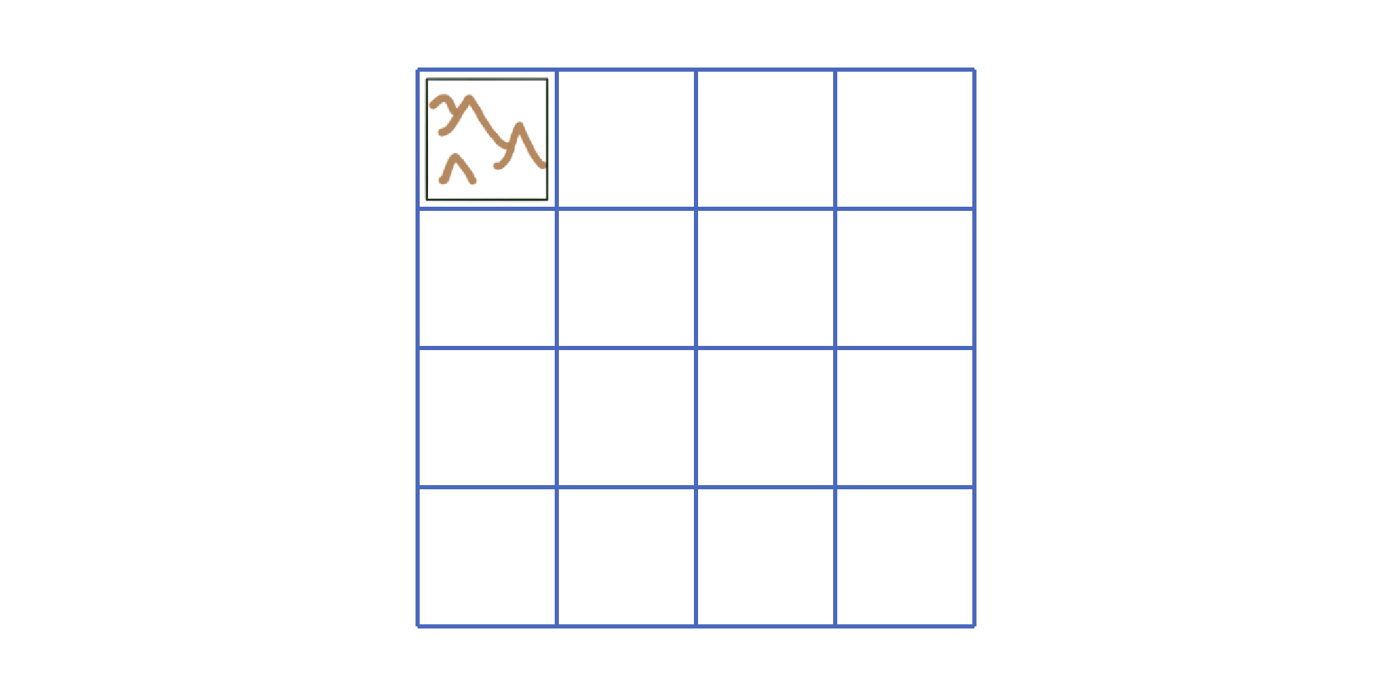
We then pick a first case on the grid and randomly select the first tile. Here, we go with a Mountain tile:
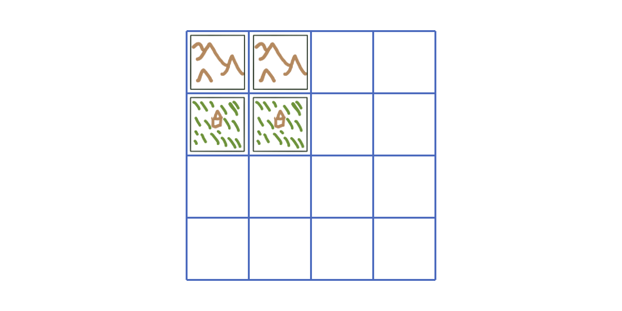
Since Mountain can only be near Land or itself, we can place the following tiles near it. If we have more than one possibility, we randomly select the tile among the possibilities:
We then keep on filling the grid, following the rules for each successive tile:
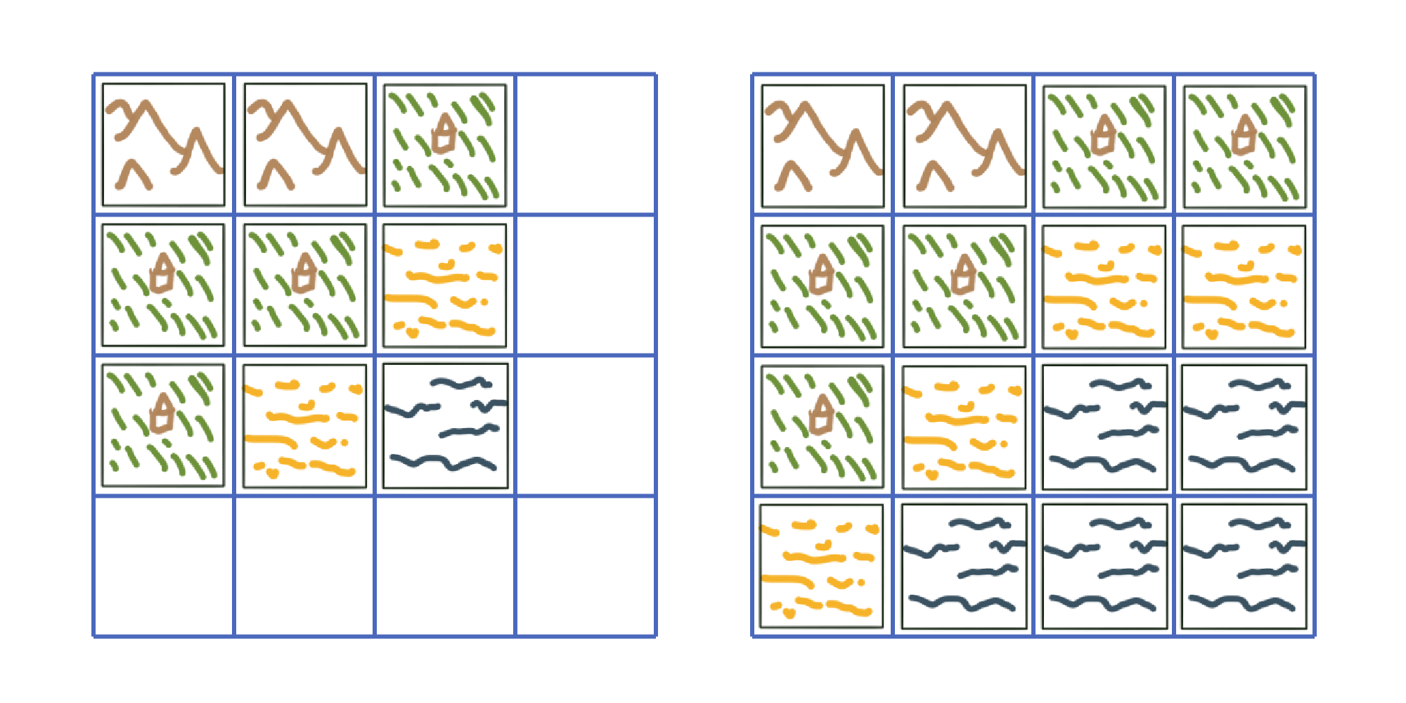
We end up with a nice landscape. With such an algorithm, you can generate a lot of landscape by changing the position or the type of the first tile. A weight system allowing the algorithm to choose among the possible tiles can also replace the random part of this implementation.
This idea seemed quite interesting for generating an office floor plan. To implement this system in Revit, I begin by drawing the tile as a Revit group. I start with a 2.70 m * 2.70 m tile. In this square, I model an office space with a partition wall and three segments of façade.
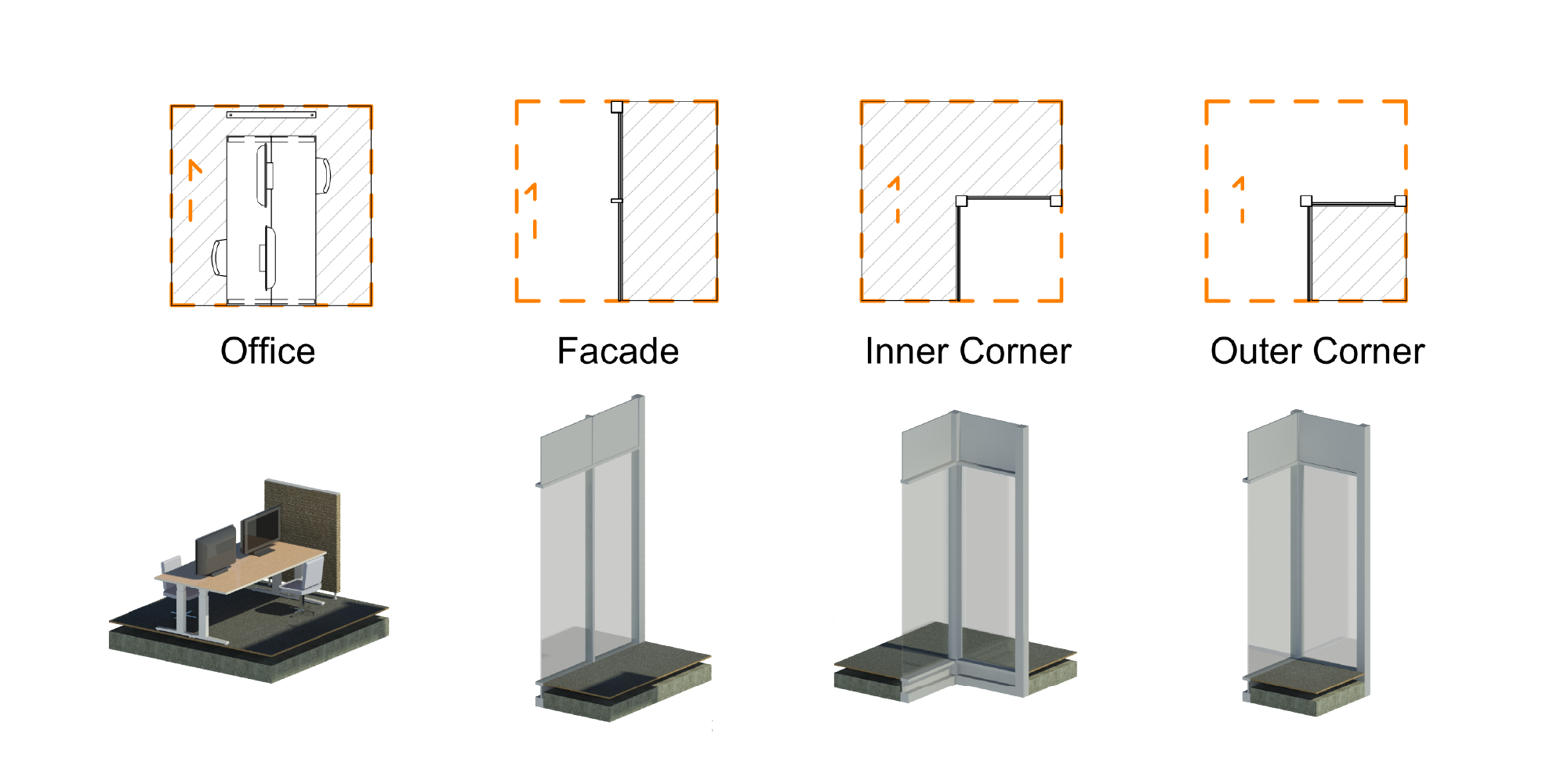
I then use a Group to create a single tile out of these models.
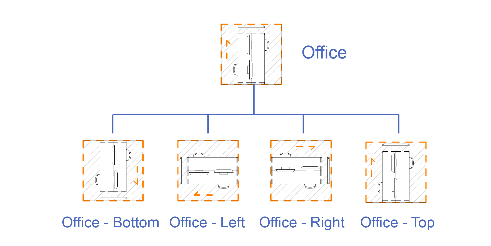
To be able to connect these tiles together, we need to rotate them. Instead of implementing the rotation on the code, I created four groups for each tile, each group containing the tile rotated a quarter turn.
We end up with 16 Revit groups that will form the basis for generating our floor plan.
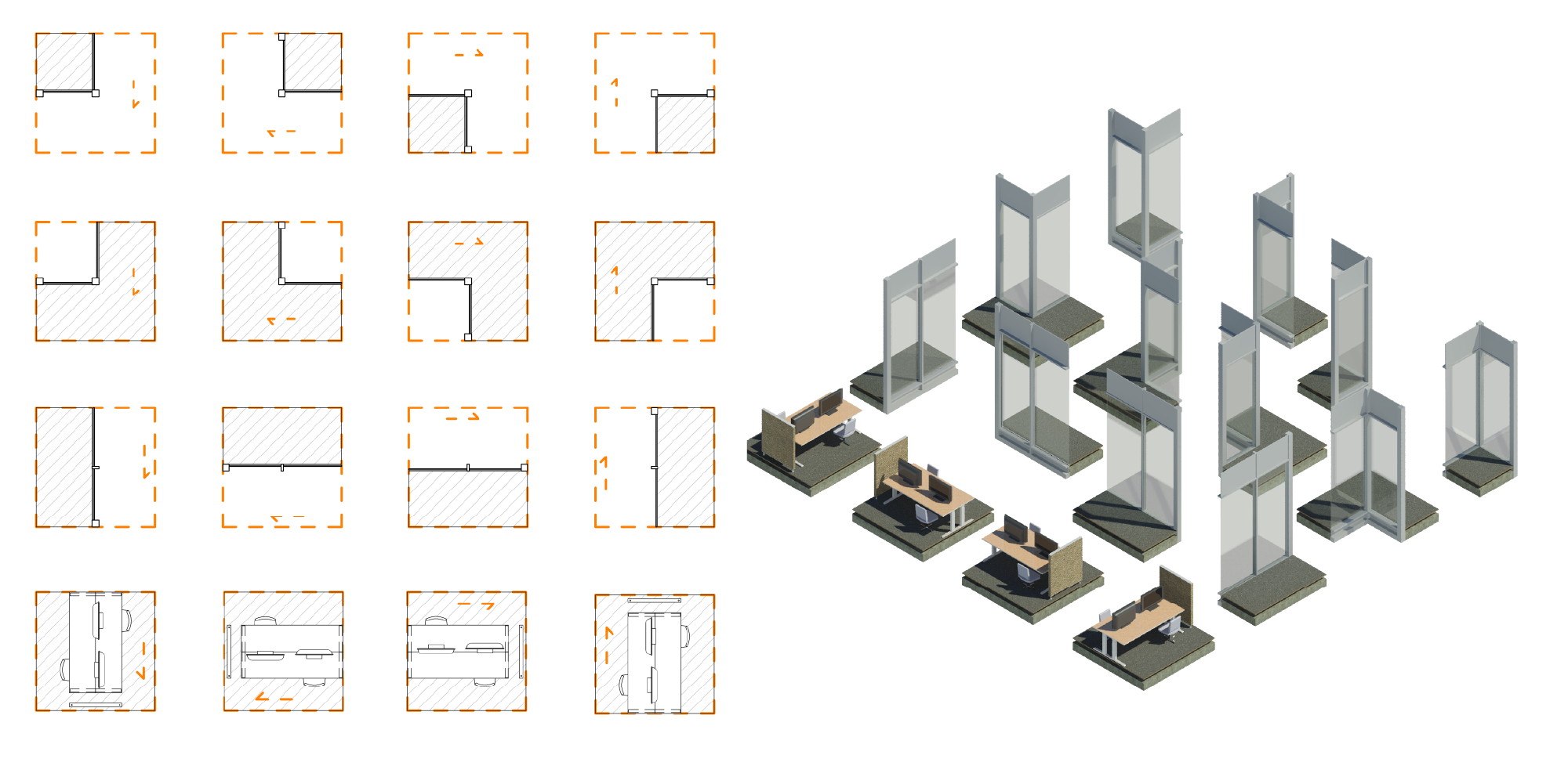
I also add a 17th group named “Void” to represent space outside the building.
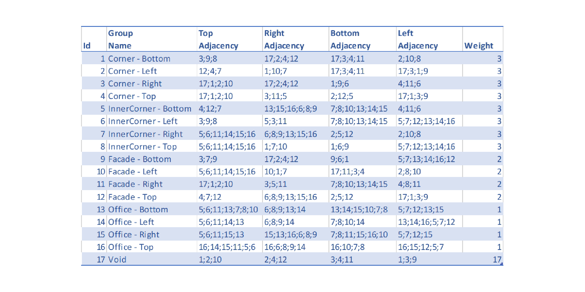
I then create an Excel spreadsheet where I formalize all adjacency rules. In this spreadsheet, I describe for each tile, i.e. each Revit group, which group can be attached above, below, on the left or on the right. The last column, “Weight”, allows to rank some tiles over the other.
I then create a C# console application containing the actual Wave Function Collapse implementation. This application takes the rules spreadsheet and output a csv file describing the resulting grid. This csv file contains the name of the group to be created for each position on the grid.
I then use this file in a small Dynamo solution to place all groups instances in the model.
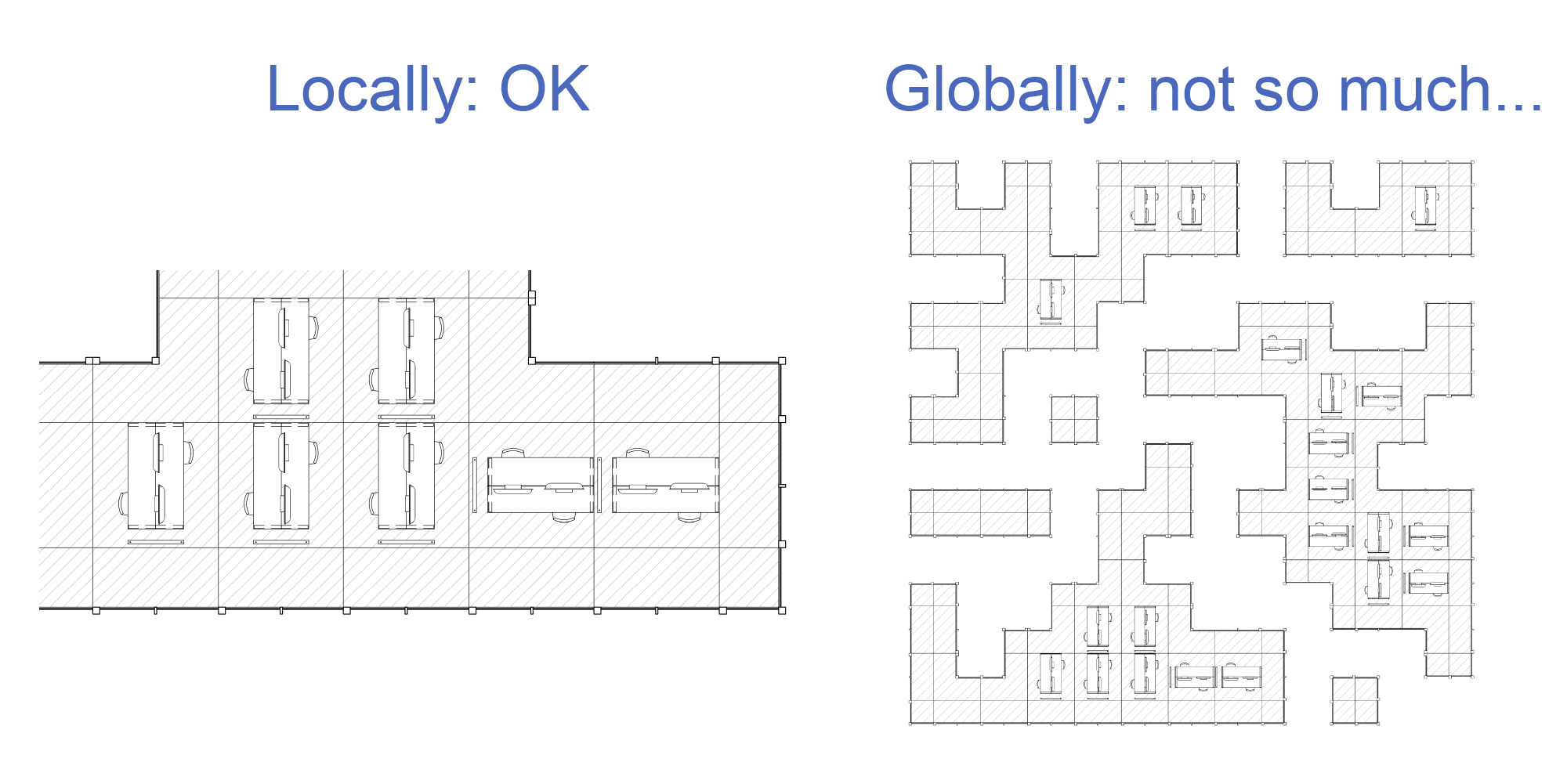
By running this process a bunch of time, I get a series of floor plans fully modelled in Revit.
Resulting layouts are not very interesting. Even if they more or less “look good”, with actual office spaces bordered by a facade, they are not credible architectural solutions. And the ability to make a lot of them will not make them any better. Since the algorithm is building the entire floor plan by only looking at the surrounding tiles, it locally seems fine, but is still a mess globally. The algorithm lacks some sort of global overview of the objective.
But even if my naive approach of using it for generating an entire floor plan will not work, the principle seems nonetheless interesting, maybe for something like facade design.
For now, the whole system is a bit tedious to run in Revit. I hope to improve it by integrating the entire code in Dynamo. I will then be able to use on different use cases.